

Bearing Positioning Tool Set
Model
KA- 2891
Specification:
- Press Block Sizes: (Material: Nylon + Fiber)
- 1.555" (39.5mm), 1.752"(44.5mm), 1.968" (50.0mm), 2.322" (59.0mm), 2.48" (63.00mm), 2.559" (65.0mm), 2.922" (76.0mm), 3.189" (81.0mm)
Description
|
|
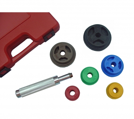
Set contains nine sizes:
1.555”(39.5mm)、1.752”(44.5mm)、1.968”(50.0mm)、2.322”(59.0mm)、2.48”(63.0mm)、2.559”(65.0mm)、2.834”(72.0mm)、2.992”(76.0mm)、3.189”(81.0mm)
In using, as shown in Figs. 1-3, firstly, pick out a positioning press block 2 with a suitable diameter and circumference according to the size of the inner diameter of a bearing (B) to be assembled.
Next, the combining rod 10 of the grip 1 is inserted through the central insert hole 20 of the positioning press block 2 and then the combining member 3 is threaded to combine with the combining threaded hole 11 of the grip 1 to fix the positioning press block 2 in position.
In operating for positioning the bearing (B), as shown in Figs. 2 and 3, firstly, the positioning press block 2 has its first fitting member 21 (or the second fitting member 23) closely contacting with the inner wall (B10) of the bearing (B) and its first holding edge 22 (or the second holding edge 24) closely and horizontally resting on the upper edge (B11) of the bearing (B)
Next, the bearing (B) is driven into the insert hole (A) of an axle by striking the hammering end 12 of the grip 1 with a hammering tool. Thus, since the positioning press block 2 has its first fitting member 21 and its first holding edge 22 respectively and horizontally contacting closely with the inner wall (B10) and the upper edge (B11) of the bearing (B): therefore, the bearing (B) can smoothly and quickly be assembled and positioned in the insert hole (A) of an axle
.jpg)
.jpg)
.jpg)
1.555”(39.5mm)、1.752”(44.5mm)、1.968”(50.0mm)、2.322”(59.0mm)、2.48”(63.0mm)、2.559”(65.0mm)、2.834”(72.0mm)、2.992”(76.0mm)、3.189”(81.0mm)
In using, as shown in Figs. 1-3, firstly, pick out a positioning press block 2 with a suitable diameter and circumference according to the size of the inner diameter of a bearing (B) to be assembled.
Next, the combining rod 10 of the grip 1 is inserted through the central insert hole 20 of the positioning press block 2 and then the combining member 3 is threaded to combine with the combining threaded hole 11 of the grip 1 to fix the positioning press block 2 in position.
In operating for positioning the bearing (B), as shown in Figs. 2 and 3, firstly, the positioning press block 2 has its first fitting member 21 (or the second fitting member 23) closely contacting with the inner wall (B10) of the bearing (B) and its first holding edge 22 (or the second holding edge 24) closely and horizontally resting on the upper edge (B11) of the bearing (B)
Next, the bearing (B) is driven into the insert hole (A) of an axle by striking the hammering end 12 of the grip 1 with a hammering tool. Thus, since the positioning press block 2 has its first fitting member 21 and its first holding edge 22 respectively and horizontally contacting closely with the inner wall (B10) and the upper edge (B11) of the bearing (B): therefore, the bearing (B) can smoothly and quickly be assembled and positioned in the insert hole (A) of an axle